Disclaimer: the information provided on this page is given as is, i.e. without warranty that you will not break your system following it. Additionally, do not expect to get support and warranty from NETGEAR if this happens.
This page documents some efforts to get a recent grsec-enabled kernel and latest Debian system running on NETGEAR ReadyNAS 102, instead of the original (Marvell/NETGEAR-patched) kernel and custom system. At the time of writing (June 2015), everything needed to support the device is now available in upstream kernel (v4.0). Check Changelog and Todo list below to see current status and progresses. This is the same kind of work I previously performed for Netgear ReadyNAS Duo v2.
As the platform are very similar and I already spent quite some time documenting Duo v2 hardware, only the main differences are given here:
- The Duo v2 is powered by a single core Marvell Kirkwood 88F6282 ARMv5TE CPU runinng at 1.6GHz when the 102 is powered by a Marvell Armada 370 ARMv7 CPU running at 1.2GHz. The latter has NX support.
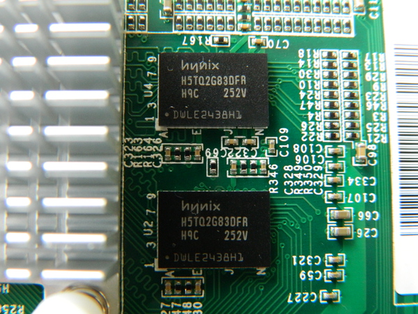
- The Duo v2 has 256MB of DDR3 RAM, the 102 comes with 512MB (2 Hynix H5TQ2G83DFRH9C chips).
- Both devices have 1 front USB2.0 port and 2 rear USB3.0 ports. Additionally; the 102 comes with an additional rear eSATA port.
- The USB3.0 controller of the Duo v2 is a NEC/RENESAS µPD720200 USB 3.0 Host Controller when the 102 includes a Fresco Logic FL1009-2Q0.
- The Duo v2 and the 102 both have a GMT G762 Fan controller and a Protechnic 92mm MGT9212YB-025 fan.
- The RTC and alarm chip of the Duo v2 is a Ricoh RS5C32A while the one in the 102 is an Intersil ISL12057.
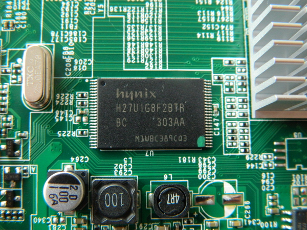
- Both devices includes 128MB of NAND (1 Hynix H27U1G8F2BTR).
Here is the main table of contents for the page, with links to the various sections of the page.
- Changelog for this page
- Remaining work in progress, i.e. TODO list
- Hardware specs
- Step by step kernel build
- Step by step Debian install
- Notes on PaX/grsec support
- Automatic fan control based on NAS temperature
- Configuring custom LED behaviour
- Configuring alarm for poweroff and automatic reboot
- Configuring custom actions for buttons
Changelog i.e. work done
- June 2015: I found some time to document how alarm support can be used for poweroff and automatic poweron of the device. See the alarm section for details on how to Configure alarm for poweroff and automatic reboot.
- February 2015: I finally managed to have alarm support patches for ReadyNAS RN102, RN202 and RN2120 using the ISL12057 RTC chip accepted in upstream kernel v4.0 (1a67e256dbd8, 298ff0122ab1, fd71493d6797). This allows you to very simply install an alarm time, power off your NAS and see it reboot at the programmed value. cron being your friend, you can very simply program different behaviours for each day of the week.
- December 2014: various cleaning patches for ISL12057 RTC chips pushed in upstream kernel (cf67d0b64101, 10df1e678764, b5f4184d1439, 5945b2880363)
- October 2014: Added a basic script to associate actions to power, reset and backup buttons.
- January 2014: After a lot of struggle due to an inactive RTC maintainer, Support for Intersil ISL12057 I2C RTC chip has been accepted usptream and will be available in 3.14 kernel. Alarm support is still missing though, i.e. you will not be able to wake-up the NAS with a mainline kernel at the moment.
- November 2013: added reference to mvneta PHY fix which required a 'ping' call in u-boot env as a lame workaround. Pushed patch to fix poweroff (available in 3.12). Pushed patch to fix Power button GPIO to make it active high (available in 3.12).
- September 2013: full update of this page, including procedure to build a kernel and install a Debian on the NAS.
- July 2013: Netgear ReadyNAS 102 .dts file accepted usptream (w/o RTC support yet) for 3.12 kernel.
- June 2013: G762/G763 PWM Fan controller driver accepted upstream. Rump at SSTIC 2013 on ReadyNAS 102 work roadmap.
- May 2013: added information on serial console pins. Got first custom running kernel on the device (3.10-rc1) using a basic custom .dts file. Work on improving initial .dts file to support more hardware parts (LED, buttons, ...).
- April 2013: Created the page. First pictures of hardware parts. First connection via 3.3V serial console (available under the sticker at the rear of the NAS). Started splitting NETGEAR/Marvell patch above 3.0.56 kernel (1.1 million lines).
Todo list i.e. work in progress
-
Document how to change default LED behaviour -
Document how to configured custom actions for buttons - Investigate the feasibility of reporting disk presence in the bay via associated LED
- Investigate the feasibility of reporting specific disk activity via associated LED
-
Work on clock drifting -
Work on poweroff -
Work on Alarm behaviour to be able to poweroff and wake the NAS at given hours - Work on progressive poweron of the disk and live insertion/removal
-
Work on throughput issue with ethernet controller -
Work on init issue with ethernet controller -
Get an initial .dts file capable of booting a userland -
Add entries for gpio LEDs in .dts file -
Add entries for gpio buttons in .dts file -
Find which GPIO activity LED is using -
Add entry for G762 fan controller in .dts file -
Fix I2C bus lock issue -
Add entry for ISL 12057 RTC chip in .dts file -
Work on upstream support for ISL12057 RTC chip -
Make USB3.0 ports working (waiting for MVEBU PCIe patches integration) -
Debug the issue w/ the ethernet PHY not been recognized -
Understand if current kernels can support NAND
Hardware Specs
This section is dedicated to the hardware specs of the NETGEAR ReadyNAS 102. It is based on visual inspection of RN102 main board and two daughter boards, completed with reading of NETGEAR 3.0.57 kernel sources and publicly available (read Google-gathered) information. This is the same method I previously used for its older brother, the ReadyNAS Duo v2.
When available, additional information and software handling details are given for each hardware part. For instance, if you are looking for informations related to the fan controller, simply click the link above to get the details of what is used and how support is provided.
Each picture available on this page is a thumbnail of a larger picture. The larger one can be accessed by clicking the thumbnail.
If you are in a hurry looking for a specific info, you can use this table of contents to directly access information on a specific hardware part of the system or get an overview of what a NETGEAR ReadyNAS 102 is made of.
- Marvell SoC Armada 370 ARMv7 @1.2Ghz
- 128 MB Hynix H27U1G8F2BTR NAND Flash
- 512 MB RAM via 2x256 Hynix DDR3 @1333Mhz
- Intersil ISL12057 I2C bus RTC
- Fresco Logic FL1009 USB 3.0 xHCI Controller
- GMT G762 PWM Fan Controller
- Protechnic Electric Co MG9212YB-25 Fan
- Main daughter board (rear ports)
- Main board front buttons and LED
- Marvell 88SE9170 PCI-e dual- port 6Gbps SATA controller
- Marvell 88E1318 Gigabit Ethernet PHY
- Serial interface via 16550A UART
- CR2032 battery
- Marvell G47B
- Richtek RT8105
- Texas instruments TPS65251
Marvell Armada 370
The ReadyNAS 102 is powered by an (ARMv7-based) Marvell ARMADA 370 SoC. The CPU comes with a FPU and NX bit support. The SoC includes a 16-bit DDR3 memory interface, two ethernet MAC controllers (one routed on the 102), two DMA/XOR engines, a network security engine, two UART interfaces, thermal support, etc. The following Armada 370 SoC block diagrams (extracted from the product brief) provides an overview of supported functionalities:
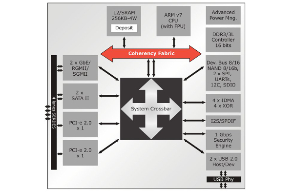
The following excerpt (also fro the product brief) provides an expected typical use of the SoC in 2 bay NAS implementations:
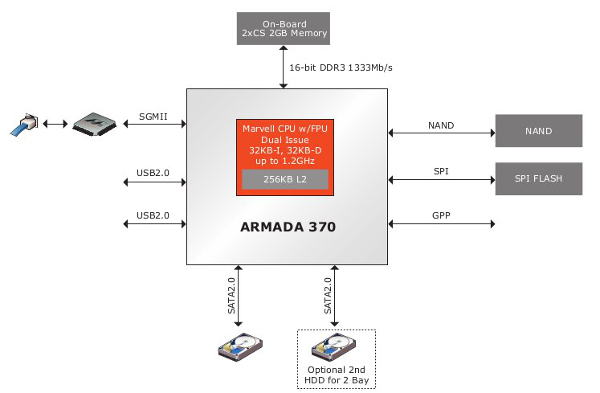
The ReadyNAS 102 uses this architecture with some additional hardware parts to support more functionalities (specific RTC with alarm support, USB 3.0, eSATA controller, etc)
Here is what /proc/cpuinfo reports for the CPU:
# cat /proc/cpuinfo
Processor	: Marvell PJ4Bv7 Processor rev 1 (v7l)
BogoMIPS	: 1196.85
Features	: swp half thumb fastmult vfp edsp vfpv3 vfpv3d16
CPU implementer	: 0x56
CPU architecture: 7
CPU variant	: 0x1
CPU part	: 0x581
CPU revision	: 1

Hardware	: Marvell Armada-370
Revision	: 0000
Serial		: 0000000000000000
Hynix H27U1G8F2BTR
The ReadyNAS 102 comes with 128MB of NAND flash. This is provided by a single Hynix H27U1G8F2BTR chip, as depicted below. The same chip was used on the ReadyNAS Duo v2.
Here is what NETGEAR default kernel reports about the NAND of the 102 and its layout:
armada-nand armada-nand.0: Init. HAL based NFC in 8bit mode with DMA Disabled using BCH 4bit ECC
NAND device: Manufacturer ID: 0xad, Chip ID: 0xf1 (Hynix NAND 128MiB 3,3V 8-bit)
Bad block table found at page 65472, version 0x01
Bad block table found at page 65408, version 0x01
mtd: no mtd-id
5 cmdlinepart partitions found on MTD device armada-nand
Creating 5 MTD partitions on "armada-nand":
0x000000000000-0x000000180000 : "u-boot"
0x000000180000-0x0000001a0000 : "u-boot-env"
0x000000200000-0x000000800000 : "uImage"
0x000000800000-0x000000c00000 : "minirootfs"
0x000000c00000-0x000008000000 : "ubi"
Hynix H5TQ2G83DFRH9C
The ReadyNAS 102 comes with 512MB of RAM connected to the SoC. This is provided by two soldered Hynix H5TQ2G83DFRH9C chips.
Intersil ISL12057 I2C bus RTC
The RaedyNAS 102 comes with an Intersil ISL12057 I2C bus RTC chip, as depicted below.
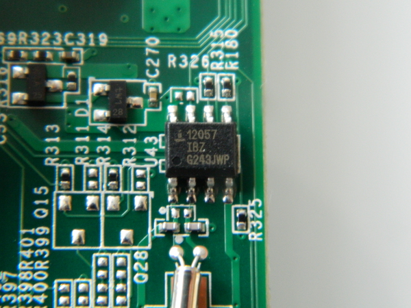
The Intersil ISL 12057 is a low power RTC and Alarm chip. A short patch (596 LoC) has been written by NETGEAR for the ReadyNAS 102 kernel (based on 3.0.56) but has never been pushed upstream. I decided to implement a driver for the chip based solely on existing ISL 12008 kernel driver and ISL12057 datasheet and push it upstream.
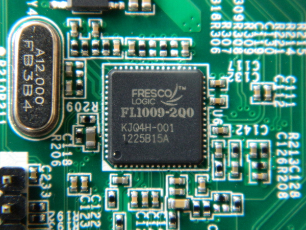
Fresco Logic FL1009 USB3.0/xHCI host controller
The USB3.0/xHCI controller used by the device is a Fresco Logic FL1009, as depicted below. A product brief is locally cached here. The FL1009 is a 2-port PCIe, which was the first one to gain USB-IF certification. It has also being demoed by Fresco Logic to hit speeds in excess of 400MB/s.
GMT G762 PWM Fan controller
The rotation speed of the fan is controlled by a GMT G762 PWM fan controller chip. Both of those (fan and controller) are the same as the one used on RN102 old brother (i.e. ReadyNAS Duo v2)
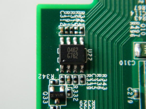
After some work, I managed to get G762 driver accepted upstream in 3.11 kernel. That been done, it can now easily be referenced in Duo v2 (done) and RN102 .dts file.
Take a look at the fancontrol section to see how the fan controller can be coupled with the temperature sensor.
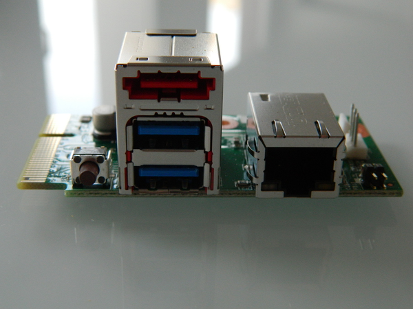
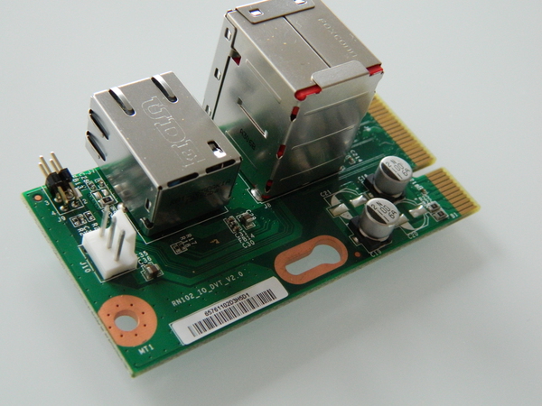
Main daughter board (USB 3.0 eSata, serial, ethernet and fan connector)
The ReadyNAS 102 mainboard has two connected daughter boards:
- The main daughter board supports all the rear connector of the device, i.e. the two USB ports, the eSata port, the ethernet, the fan connector and the serial console pins.
- The second daughter board holds the two SATA connectors for the disks.
The main daughter board is depicted below.
Mainboard front buttons and LED
The following picture provides an overview of the five leds, two buttons (Power and USB copy) and the USB port available on the front of the device, under the enclosure.
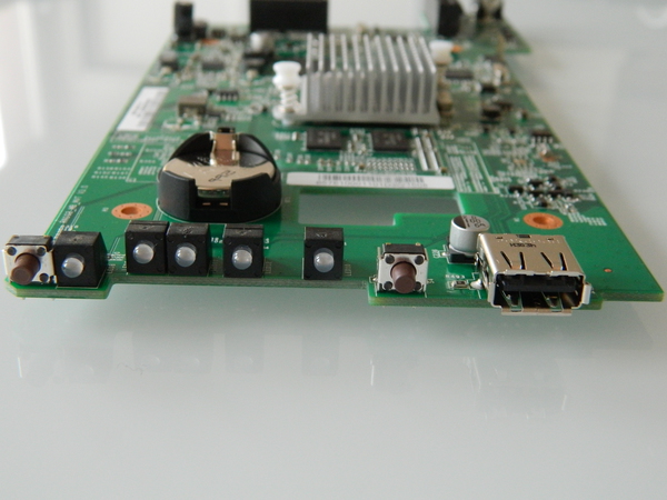
The four power (#1 from left to right on the picture), SATA1 (#3), SATA2 (#4) and backup (#5) LEDs are all connected to specific MPP of the SoC configured as GPIO (respectively MPP 57, 15, 14 and 56) and can be controlled easily from userland. The activity LED (#2) is on the contrary connected directly to the SATA controller and will flash upon activity.
In the .dts I pushed upstream to support the NAS (available in 3.12), the default initial behavior of those LEDs is the following:
- Power LED: configured for "heartbeat" behavior as described in kernel documentation, i.e. it "double" flashes at a load average based rate.
- SATA1 and SATA2 LED: configured with a default "on" state. This is a change from NETGEAR's vanilla kernel in which the LED indicates presence of a disk in the associated bay. AFAICT, there is no easy way to provide a similar behavior in mainlin kernel at the moment.
- Backup LED: just like previous LED, it is configured to be "on" by default.
The initial behaviour (state, trigger) provided in the .dts file can be modified very easily via /sys entries. This is described in more details in a specific section (Configuring custom LED behaviour) below.
Regarding the Power and Backup buttons, they are also connected to specific MPP of the SoC configured as GPIO. When pressed, they generate a signal on the referenced pin of the SoC which is converted as an input event by the kernel. In the .dts,
- The Power button is configured to generate a KEY_POWER event (code 116)
- The Rest button is configured to generate a KEY_COPY event (code 133)
Those can easily be catched from userspace in order to act upon their reception and perform specific actions. This is described in more details in a specific section (Configuring custom actions for buttons) below.
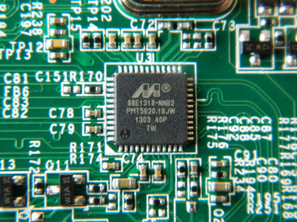
Marvell 88E1318 Gigabit Ethernet PHY
The Marvell ARMADA 370 SoC comes with two integrated Ethernet MAC but does not include the required PHY. The ReadyNAS 102 has a Marvell 88E1318 Gigabit Ethernet PHY connected to the SoC via a RGMII interface.
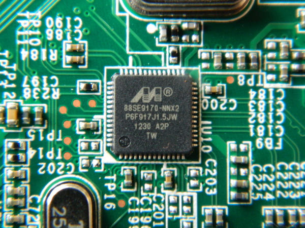
Marvell 88SE9170-NNX2 Sata Controller
The ReadyNAS 102 includes a specific Marvell 88SE9170 2 ports PCIe 2.0 1X SATA storage controller
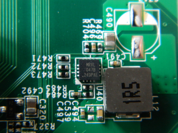
Marvell G47B
Protechnic Electric Co MG9212YB-25 Fan

The fan on the 102 is the same as the one found on its old brother, the Duo v2, i.e. a 92mmx92mmx25mm Protechnic Electric CO MG9212YB-25 Fan a Protechnic Electric Co MG9212YB-25 Fan.
Richtek RT8105
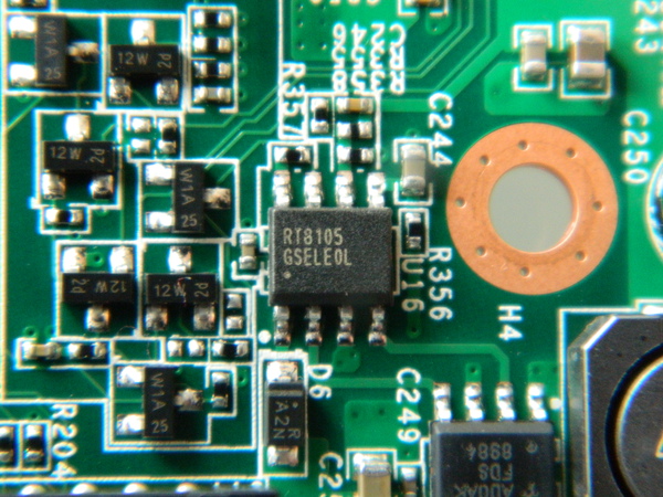
I kept a local copy of the datasheet.
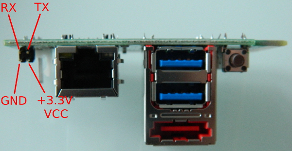
Serial interface / Console
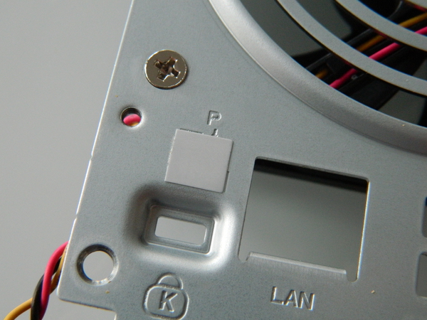
Marvell SoC directly embbeds two UARTs. In the NAS, one is rooted up to the main daughter board and associated pins are directly available under a simple sticker at the rear of the device, on the left side above the kensington port, as depicted above.
Once the sticker removed, the four pins of the serial console on the main daughter board can be used to get access to the device. Note that the serial port is a 3.3V one, i.e. you need a specific adapter like the one depicted below and cannot use a usual 12V serial or USB serial dongle for that purpose..
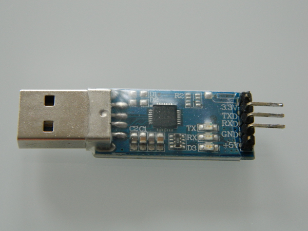
The specific purpose of each pin is depicted below
Below is what default NETGEAR kernel reports about the serial console.
Serial: 8250/16550 driver, 2 ports, IRQ sharing disabled
serial8250.0: ttyS0 at MMIO 0xd0012000 (irq = 41) is a 16550A
console [ttyS0] enabled
and what 3.11 reports about it:
Serial: 8250/16550 driver, 2 ports, IRQ sharing disabled
d0012000.serial: ttyS0 at MMIO 0xd0012000 (irq = 17) is a 16550A
console [ttyS0] enabled, bootconsole disabled
Texas Instruments - TPS65251
This is the same chip as on Netgear ReadyNAS Duo v2.
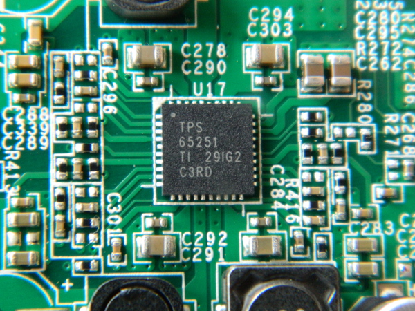
I kept a local copy of the datasheet just in case you have
CR2032 Battery
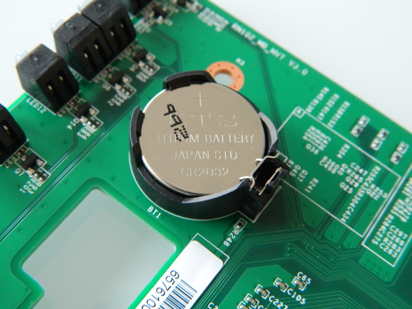
The CR2032 battery is used to provide power to the ISL 12057 RTC chip when the NAS is not powered.
Step by step kernel build
This section documents in details a step by step build and install of a 3.11.1 kernel on the ReadyNAS Duo v2. The steps should be similar for a more recent kernel version. The procedure described in this section is very similar to the one given for ReadyNAS Duo v2. Although this creates duplication, this makes the page self-sufficient.
Cross-compilation toolchain
The first thing needed to compile the kernel is a cross-compilation toolchain. Assuming you are on Debian, you could previously just use emdebian.org repositories to get the required packages:
root@small# cat > /etc/apt/sources.list.d/emdebian.sources.list
deb http://www.emdebian.org/debian unstable main
^D
root@small# apt-get update
root@small# apt-get install binutils-arm-linux-gnueabi \
                            gcc-4.7-arm-linux-gnueabi \
                            libgcc1-armel-cross \
                            linux-libc-dev-armel-cross
Now (2014), the best way to get a proper cross-compilation toolchain is to build one using crosstool-ng. It is straigthforward to get an arm-unknown-linux-gnueabi one.
Here, we could also use an arm-[unknown-]linux-gnueabihf- toolchain (Armada 370 has a FPU) instead of the arm-[unknown-]linux-gnueabi- one. Even though I did not performed specific tests, this should have no performance impact for kernel whereas it may have on userland for specific applications.
Kernel Build
Now that we have a compiler to create arm binaries, let's first grab our kernel.
arno@small$ wget https://www.kernel.org/pub/linux/kernel/v3.x/linux-3.11.1.tar.xz
arno@small$ wget https://www.kernel.org/pub/linux/kernel/v3.x/linux-3.11.1.tar.sign
arno@small$ gpg --verify linux-3.11.1.tar.sign
gpg: Signature made Sat 14 Sep 2013 04:07:21 PM CEST using RSA key ID 6092693E
gpg: Good sig. from "Greg KH (Linux kernel stable release signing key) <greg@kroah.com>"
arno@small$ tar xf linux-3.11.1.tar
As 3.11 kernel is still missing RN102 .dts file (which will be available in 3.12) and ISL 12057 RTC chip support, we need to patch the kernel to complete the support:
arno@small$ wget http://natisbad.org/NAS2/linux-3.11.1-rn102-support.patch
arno@small$ wget http://natisbad.org/NAS2/linux-3.11.1-rn102-support.patch.sign
arno@small$ gpg --verify linux-3.11.1-rn102-support.patch.sign
gpg: Signature made Sun 29 Sep 2013 07:27:05 PM CEST using RSA key ID A7AE341B
gpg: Good signature from "Arnaud Ebalard <arno@natisbad.org>"
arno@small$ cd linux-3.11.1
arno@small$ patch -p1 -i ../linux-3.11.1-rn102-support.patch
patching file arch/arm/boot/dts/armada-370-netgear-rn102.dts
patching file arch/arm/boot/dts/Makefile
patching file drivers/rtc/Kconfig
patching file drivers/rtc/Makefile
patching file drivers/rtc/rtc-isl12057.c
Let's now configure the kernel. In order to bootstrap with a working config and then make it fit your needs feature-wise, the best way is to use the one I provide below:
arno@small$ wget -O .config http://natisbad.org/NAS2/config-rn102-3.11.1
arno@small$ export ARCH=arm
arno@small$ export CROSS_COMPILE=arm-linux-gnueabi-
arno@small$ make oldconfig
  HOSTCC  scripts/basic/fixdep
  HOSTCC  scripts/kconfig/conf.o
  SHIPPED scripts/kconfig/zconf.tab.c
  SHIPPED scripts/kconfig/zconf.lex.c
  SHIPPED scripts/kconfig/zconf.hash.c
  HOSTCC  scripts/kconfig/zconf.tab.o
  HOSTLD  scripts/kconfig/conf
scripts/kconfig/conf --oldconfig Kconfig
#
# configuration written to .config
#
arno@small$ make menuconfig
The last make menuconfig allow you to change the kernel configuration to fit your needs.
Let's now build the kernel zImage, append to it our Netgear ReadyNAS 102 .dtb (Device Tree Blob) generated from our .dts (Device Tree Source) file and then make a uImage out of it. The resulting uImage is then copied to our tftp folder to be served to the NAS to be loaded by u-boot. So, in the same shell (where ARCH and CROSS_COMPILE where previously defined):
arno@small$ LOADADDR=0x00008000 make -j 16
arno@small$ cat arch/arm/boot/dts/armada-370-netgear-rn102.dtb >> arch/arm/boot/zImage
arno@small$ LOADADDR=0x00008000 make uImage
arno@small$ sudo cp arch/arm/boot/uImage /srv/tftp/
tftp setup to serve kernel image (and later Debian installer).
The best way to push required binaries (kernel images, debian installer) to the NAS is probably via tftp. This is done quite simply from your Debian host by installing openbsd-inetd and atftpd packages (I got issues with tftpd packages so I would suggest not to use it). If you have a firewall running on your host, you need to temporarily allow incoming connection on 69/udp.
arno@small$ sudo apt-get install openbsd-inetd atftpd
arno@small$ sudo /etc/init.d/openbsd-inetd restart
arno@small$ sudo iptables -A INPUT -i eth0 -p udp --dport 69 -j ACCEPT
From now on, everything we put in /srv/tftp will be accessible from u-boot, which will allow us to boot the kernel image we built and put there for example. But to interact with u-boot, we need to access to the serial console.
Serial access to u-boot and system console
Details of serial console access is described in hardware section.
Then, once our 3.3V USB/serial dongle is connected on one side to the serial console of the RN102 and on the other to an USB port of our host, we can simply plug the power cord without powering the device. The following appears:
arno@small$ screen /dev/ttyUSB0 115200

BootROM 1.08
Booting from NAND flash
DDR3 Training Sequence - Ver 2.1.7
DDR3 Training Sequence - Ended Successfully
BootROM: Image checksum verification PASSED

 __   __                      _ _
|  \/  | __ _ _ ____   _____| | |
| |\/| |/ _` | '__\ \ / / _ \ | |
| |  | | (_| | |   \ V /  __/ | |
|_|  |_|\__,_|_|    \_/ \___|_|_|
         _   _     ____              _
        | | | |   | __ )  ___   ___ | |_
        | | | |___|  _ \ / _ \ / _ \| __|
        | |_| |___| |_) | (_) | (_) | |_
         \___/    |____/ \___/ \___/ \__|
 ** LOADER **


U-Boot 2009.08 (Feb 07 2013 - 11:13:03)Marvell version: 1.1.2 NQ
02/07/2013 ReadyNAS-102N104 V1.9
U-Boot Addressing:
       Code:            00600000:006AFFF0
       BSS:             006F9240
       Stack:           0x5fff70
       PageTable:       0x8e0000
       Heap address:    0x900000:0xe00000
Board: DB-88F6710-BP
SoC:   MV6710 A1
CPU:   Marvell PJ4B v7 UP (Rev 1) LE
       CPU @ 1200Mhz, L2 @ 600Mhz
       DDR @ 600Mhz, TClock @ 200Mhz
       DDR 16Bit Width, FastPath Memory Access
PEX 0: Root Complex Interface, Detected Link X1
PEX 1: Root Complex Interface, Detected Link X1
DRAM:  512 MB
       CS 0: base 0x00000000 size 512 MB
       Addresses 14M - 0M are saved for the U-Boot usage.
NAND:  (ID 0xf1ad)      128 MiB
Bad block table found at page 65472, version 0x01
Bad block table found at page 65408, version 0x01
FPU not initialized
USB 0: Host Mode
USB 1: Host Mode
Shutting down unused interfaces:
       GBE0
       SDIO
       AUDIO
       TDM
Modules/Interfaces Detected:
       RGMII1 Phy
       PEX0 (Lane 0)
       PEX1 (Lane 1)
       SATA0 (Lane 2)
       SATA1 (Lane 3)
Power supply plug on, please press power button!
We can then power on the device (push the power button on the front of the device). This will present a 3 seconds countdown which allow us to interrupt the boot process and access u-boot, simply by hitting a key. Let's do just that.
Power On!

MMC:   MRVL_MMC: 0
Net:   egiga1 [PRIME]
Hit any key to stop autoboot:  0
Marvell>>
For the record, let's just print current u-boot environment
Marvell>> printenv
ethaddr=00:50:43:00:02:02
eth1addr=2C:B0:5D:BF:2E:ED
SerialNum=3ER133ET00672
Product=ReadyNAS 102
SKUNum=RN102
UUID=824db5e4-9648-11e2-a6b3-2cb05dbf2eed
Manufacturer=NETGEAR
Version=V1.0
AC_Power_fail_detect=open
console=console=ttyS0,115200
mtdids=nand0=armada-nand
mtdparts=mtdparts=armada-nand:4m(boot),-(rootfs)
sata_delay_reset=0
enaExtDisk=no
MALLOC_len=5
ethprime=egiga1
bootargs_root=root=/dev/nfs rw
bootargs_end=:10.4.50.254:255.255.255.0:KW40:eth0:none
image_name=uImage
load_addr=0x02000000
bootcmd=nand read 0x2000000 0x200000 0x400000;nand read 0x30000000x800000 0x400000;bootm      \
        0x2000000 0x3000000 standalone=fsload $load_addr $image_name;setenv bootargs $console \
        $mtdparts root=/dev/mtdblock0 rw ip=$ipaddr:$serverip$bootargs_end; bootm $load_addr;
bootdelay=3
ethmtu=1500
eth1mtu=1500
mvNetConfig=mv_net_config=1,(00:50:43:11:11:11,0:1:2:3:4),mtu=1500
usb0Mode=host
usb1Mode=host
usbActive=0
yuk_ethaddr=00:00:00:EE:51:81
nandEcc=1bit
netretry=no
rcvrip=169.254.100.100
loadaddr=0x02000000
autoload=no
eeeEnable=no
HW_version=MVT
Startup=Normal
ethact=egiga1
ipaddr=192.168.58.21
serverip=192.168.58.135
mainlineLinux=yes
stdin=serial
stdout=serial
stderr=serial
enaMonExt=no
pexMode=RC
setL2CacheWT=no
sata_dma_mode=yes
netbsd_en=no
vxworks_en=no
disaMvPnp=no
enaAutoRecovery=yes
pcieTune=no
bootargs=console=ttyS0,115200 mtdparts=armada-nand:0x180000@0(u-boot),                        \
         0x20000@0x180000(u-boot-env),0x600000@0x200000(uImage),                              \
         0x400000@0x800000(minirootfs),-(ubi); reason=normal bdtype=rn102

Environment size: 1500/131068 bytes
As you can see, the environment contains the expected address of the tftp server (serverip parameter) and the NAS IP address (ipaddr):
...

Net:   egiga0 [PRIME]
Hit any key to stop autoboot:  0
Marvell>> printenv
...
ipaddr=192.168.58.21
serverip=192.168.58.135
...
As you can see above, u-boot environment expects the tftp server to be available at IP address 192.168.58.135. Let's just configure that adress on our host:
arno@small# sudo ip addr add 192.168.58.135/24 dev eth0
Booting your first kernel
Let's now load kernel image we built (uImage) in memory at address 0x1200000
Marvell>> tftpboot 1200000 uImage
Using egiga1 device
TFTP from server 192.168.58.135; our IP address is 192.168.58.21
Filename 'uImage'.
Load address: 0x1200000
Loading: #################################################################
         #################################################################
         #################################################################
         #######################################################
done
Bytes transferred = 3667163 (37f4db hex)
Now that we have our kernel uImage loaded in RAM at address 0x1200000, we can try and check if the kernel boots by issuing the following command:
Marvell>> set serverip 192.168.58.135
Marvell>> set ipaddr 192.168.58.21
Marvell>> set bootargs console=ttyS0,115200 earlyprintk
Marvell>> bootm 0x1200000
This should fail at some point (e.g. no root device) but this is a good test before proceding to the next section.
Step by step Debian install
Now that we have a working kernel, the next step is boot it and use an initrd version of a debian installer to install the system. So the first step is to get a Debian installer. As the Armada 370 SoC has an FPU, we can either use an armel or armhf one, depending on the kind of Debian package architecture we want. In practice, there is no specific reason not go for an armhf installer. For that purpose, you can use current Efikamx mx5 one (or a local working copy (Sep 24 2013)).
Now, considering you choosed the current uInitrd Debian installer and both the kernel and the installer are in your tftp server folder:
Marvell>> set bootargs console=ttyS0,115200 earlyprintk
Marvell>> tftpboot 1200000 uImage
Using egiga1 device
TFTP from server 192.168.58.135; our IP address is 192.168.58.21
Filename 'uImage'.
Load address: 0x1200000
Loading: #################################################################
         #################################################################
         #################################################################
         #######################################################
done
Bytes transferred = 3667163 (37f4db hex)
Marvell>> tftpboot 2000000 uInitrd
Using egiga1 device
TFTP from server 192.168.58.135; our IP address is 192.168.58.21
Filename 'uInitrd'.
Load address: 0x2000000
Loading: #################################################################
         #################################################################
         #################################################################
         #################################################################
         #################################################################
         #######################################################
done
Bytes transferred = 5485034 (53b1ea hex)
Marvell>> bootm 0x1200000 0x2000000
At that point, you should be at home and be able to complete the install of the system as usual. Based on the number of disks, their size and your RAID/lvm setup, you should either be able to boot directly the main partition of your disk (say /dev/sda1) or you may need an uInitramfs.
Building an uInitramfs (required for large disk w/ GPT partitions and/or LVM/RAID installs)
Once Debian install is over, you can reboot the NAS and use the process above to boot again the kernel and the Debian installer. This time, the idea is to get up to the partition manager so that all your partitions (raid, lvm, ext4) are set up and mounted. By executing a shell, we will create an initramfs and then install the kernel and this initramfs (as a replacement of NETGEAR ones on the NAND flash). So, from the Debian installer shell you can remount your disk. Below the root system is on a lvm volume - /dev/mapper/vgr-lvr - but yours could be on something like /dev/sda1 if you did something simple:
root@humble# cd /
root@humble# mkdir tgt
root@humble# mount /dev/mapper/vgr-lvr /tgt
root@humble# cd tgt
root@humble# mount -o bind /proc proc/
root@humble# mount -o bind /dev dev/
root@humble# mount -o bind /dev/pts dev/pts
root@humble# mount -o bind /sys sys
root@humble# chroot . /bin/bash
Let's install initramfs tools, build one ...
root@humble# apt-get install initramfs-tools
root@humble# mkinitramfs -o /tmp/initramfs-3.11.1 -r /dev/mapper/vgr-lvr -v
... , and make it understandable by u-boot:
root@humble# apt-get install uboot-mkimage
root@humble# mkimage -A arm -O linux -T ramdisk -C none -a 0x00000000 -e 0x00000000 \
                  -n initramfs -d /tmp/initramfs-3.11.1  /tmp/uInitramfs
Once this is done, you can save the generated uInitramfs; for instance to a USB key. The idea is to be able to make it available in next section via tftp, USB or disk.
Also note that based on your root device (/dev/mapper/vgr-lvr here), you will also have to change the bootargs command in order to provide that information to the kernel (possibly with an additional rootdelay option). In our case:
Marvell>> set bootargs console=ttyS0,115200 earlyprintk root=/dev/mapper/vgr-lvr
Marvell>> saveenv
Boot strategies
Upon boot, the NAS will load u-boot, which will then - based on the content of its environment - load at least an uImage (and possibly an uInitramfs) from some given location and start your favourite distribution, most probably available on SATA disks.
In practice, the main factor impacting the boot strategies available to you is the size of the disks put in the NAS. If you put large disks (say more than 2TB), then those will be partitioned with a GPT which will prevent installing and load the kernel from a partition (say /boot) available on the disk. In that case, the only available methods are to load the kernel from NAND, a USB key or tftp.
Additionally, if you intend to install the system on a RAID/lvm (say ext4 on LVM on a two disks software RAID1 array), even if you are able to load the kernel, you will not be able to go any further without using an uinitramfs because Linux kernel can not automount RAID array.
In the end, the best method is probably to have u-boot load both an uImage and an uInitramfs from NAND (or USB).
Anyway, the three methods are all described below.
Booting from NAND
IMHO, the most simple way to store and boot an uImage (and possibly an uInitramfs) is to put those in NAND and get them loaded via u-boot at startup. This is basically the purpose of the NAND and how NETGEAR uses it. From the bootloader, you can see how the NAND is partitioned:
Marvell>> nand info
Device 0: nand0, sector size 128 KiB

Marvell>> printenv
...
mtdparts=nand_mtd:
0x180000@0(u-boot)
0x20000@0x180000(u-boot-env)
0x600000@0x200000(uImage)
0x1000000@0x800000(minirootfs)
0x6800000@0x1800000(jffs2)
...
It contains (in that order) some space for u-boot itself (1536 KB), u-boot environment (128 KB), kernel uImage (6 MB) and a rootfs/initrd (16 MB) and a jffs2 partition (104 MB).
As discussed earlier, the funny part is that NAND controller support is not available in mainline kernel (3.11 at the time of writing). For that reason, the only way to install uImage and uInitramfs in NAND is from u-boot.
So let's first load our kernel in RAM at address 0x1200000 via tftp, erase kernel partition and then write the kernel to it from RAM:
Marvell>> tftpboot 0x1200000 uImage
Using egiga1 device
TFTP from server 192.168.58.135; our IP address is 192.168.58.21
Filename 'uImage370'.
Load address: 0x1200000
Loading: #################################################################
         #################################################################
         #################################################################
         ######################################
done
Bytes transferred = 3411987 (341013 hex)

Marvell>> nand erase 0x200000 0x600000
NAND erase: device 0 offset 0x200000, size 0x600000
Erasing at 0x7e0000 -- 100% complete.
OK

Marvell>> nand write 0x1200000 0x200000 0x600000

NAND write: device 0 offset 0x200000, size 0x600000
 6291456 bytes written: OK
Then, we can do the same for our uinitramfs by loading it in RAM at address 0x2000000:
Marvell>> tftpboot 0x2000000 uinitramfs-3.11.1
Using egiga1 device
TFTP from server 192.168.58.135; our IP address is 192.168.58.21
Filename 'uinitramfs-3.11.1'.
Load address: 0x2000000
Loading: #################################################################
         #################################################################
         #################################################################
         ##########################
done
Bytes transferred = 3238266 (31697a hex)

Marvell>> nand erase 0x800000 0x400000
NAND erase: device 0 offset 0x800000, size 0x400000
Erasing at 0xbe0000 -- 100% complete.
OK

Marvell>> nand write 0x2000000 0x800000 0x400000

NAND write: device 0 offset 0x800000, size 0x400000
 4194304 bytes written: OK
Then, in order to actually have u-boot automatically load those elements from NAND at startup and boot them, we need to update bootcmd to the following and then save the environment:
Marvell>> set bootcmd "nand read 0x1200000 0x200000 0x600000; \
                       nand read 0x2000000 0x800000 0x400000; \
                       ping 192.168.58.135; \
                       bootm 0x1200000 0x2000000"

Marvell>> saveenv
Saving Environment to NAND...
Erasing 0x180000 - 0x1a0000:    [Done]
Writing to Nand:                [Done]
You might wonder why the ping call in previous command. This is to temporarily workaround what seems to be an ethernet PHY initialization issue. If you do not force u-boot to init the PHY, then the ethernet interface will not work properly when the system has booted. Well, the issue was fixed in 3.12 and backported in stable kernels. So, if your kernel is recent enough, everything should work as expected.
Booting from USB
WORK IN PROGRESSBooting from SATA disk
WORK IN PROGRESSNotes on PaX/grsec support
Working PaX/grsec configurations for recent kernels are available from that page.
Making MAC address stable
This is not per se a real issue but the MAC address of the RN102 available from the u-boot environment is not automatically set during the boot process. At the time of writing no good solution has been found by the kernel maintainers. In the future, the idea is for Marvell to release updated bootloader version which will modify the DTB before handling it out to the kernel and will thus be able to set expected MAC addresses.
Anyway, until this happens, the only proper^W way to get a stable MAC address is to have a userspace script set it during boot before having the interface configured. On Debian, this easily done using the following snippet in /etc/network/interfaces:
root@humble:~# cat /etc/network/interfaces
auto lo
iface lo inet loopback

auto eth0
iface eth0 inet dhcp
        pre-up ip link set dev eth0 address 00:50:44:00:02:02
Automatic fan control based on NAS temperature
After having installed fancontrol package ...
root@humble:/sys/bus/i2c# apt-get install fancontrol
... , you first need to run pwmconfig to create an initial configuration referencing the temperature sensor and the fan controller, and the various temperature and fan rotation limits. You will end up with a configuration file (/etc/fancontrol)like the following (stock 3.11 kernel):
root@humble:/sys/bus/i2c# cat /etc/fancontrol
# Configuration file generated by pwmconfig, changes will be lost
INTERVAL=5
DEVPATH=hwmon0=devices/soc.0/internal-regs.1/d0011000.i2c/i2c-0/0-003e hwmon1=
DEVNAME=hwmon0=g762 hwmon1=armada_thermal
FCTEMPS=hwmon0/device/pwm1=hwmon1/temp1_input
FCFANS= hwmon0/device/pwm1=hwmon0/device/fan1_input
MINTEMP=hwmon0/device/pwm1=40
MAXTEMP=hwmon0/device/pwm1=60
MINSTART=hwmon0/device/pwm1=40
MINSTOP=hwmon0/device/pwm1=40
MINPWM=40
MAWPWM=175
Obviously, you may change the configuration (e.g. modify MAXTEMP and/or MAXPWM values) based on your needs (noise vs SoC temperature).
As a side note, I do not go here into the details of the fan driving mode (PWM vs DC) and the fan speed control modes (manual i.e. open-loop and automatic i.e. closed-loop) the g762 fan controller supports. By default, Netgear's u-boot puts g762 driver in manual fan speed control (/sys/bus/i2c/drivers/g762/0-003e/pwm1_enable is set to 1) and DC mode (/sys/bus/i2c/drivers/g762/0-003e/pwm1_mode set to 0). Addditional information is available in kernel g762 documentation (Documentation/hwmon/g762).
Configuring custom LED behaviour
WORK IN PROGRESSConfiguring custom actions for buttons
As discussed earlier, the 3 buttons available on the board (Power and Backup at the front, Reset at the rear) are all defined (in .dts file) to report a specific input type when pressed. By increasing kernel log level (man 5 proc), you can observe that behaviour on the console (on a kernel configured with CONFIG_INPUT_EVBUG). This will also appear in your syslog file:
root@humble# echo 8 > /proc/sys/kernel/printk
evbug: Event. Dev: input0, Type: 1, Code: 116, Value: 1             <- pressing Power button
evbug: Event. Dev: input0, Type: 0, Code: 0, Value: 0
evbug: Event. Dev: input0, Type: 1, Code: 116, Value: 0             <- releasing Power button
evbug: Event. Dev: input0, Type: 0, Code: 0, Value: 0
evbug: Event. Dev: input0, Type: 1, Code: 133, Value: 1             <- pressing Backup button
evbug: Event. Dev: input0, Type: 0, Code: 0, Value: 0
evbug: Event. Dev: input0, Type: 1, Code: 133, Value: 0             <- releasing Backup button
evbug: Event. Dev: input0, Type: 0, Code: 0, Value: 0
evbug: Event. Dev: input0, Type: 1, Code: 408, Value: 1             <- pressing Reset button
evbug: Event. Dev: input0, Type: 0, Code: 0, Value: 0
evbug: Event. Dev: input0, Type: 1, Code: 408, Value: 0             <- releasing Reset button
evbug: Event. Dev: input0, Type: 0, Code: 0, Value: 0
root@humble# echo 1 > /proc/sys/kernel/printk
A possible way to configure custom actions when the button is pressed would be to continuously monitor /dev/input/event0 output (see Documentation/input/input.txt). But that would require parsing binary data in the following format:
struct input_event {
	struct timeval time;
	unsigned short type;
	unsigned short code;
	unsigned int value;
};
We could develop something in C to monitor the flow of events and perform dedicated actions upon occurrence of a given event but that would be overkill considering this can more easily be done in Python with something like the following. You can use this script as a basis.
Configuring alarm for poweroff and automatic reboot
Alarm IRQ pin (IRQ#2) of ISL12057 RTC chip is not directly connected to the SoC on RN102, RN104 and RN2120, but to a PMIC (TPS65251), handling powering of the device. The PMIC does not provide a way to report the status of the IRQ#2 pin. This is not a common design pattern on Linux and requires some specific kernel adaptation. This is the reason why alarm support (1a67e256dbd8, 298ff0122ab1, fd71493d6797) for those NAS took a bit longer than expected. If you are interested by the details, the commit messages and the code provides more information.
As also documented in alarm support commits, using the alarm feature now available on the device is very simple. Here is a straightforward example of how this can be done:
# echo `date '+%s' -d '+ 1 minutes'` > /sys/class/rtc/rtc0/wakealarm
# shutdown -h now
After having configured the alarm one minute in the future, and then having powered off the system, you should see it come back to life after a minute. Now, if you want to poweroff the device each night and have it come back say in the morning or in the afternoon, you simply need to create a crontab. This is left as an exercise for the reader.